


Cone-Beam Computed Tomography (CBCT) Applications in Dentistry
Course Number: 531
Course Contents
Image Acquisition and Reconstruction
There are two phases in CBCT imaging: the acquisition phase and the reconstruction phase. During the acquisition phase, the patient is positioned into the machine with the head stabilized to avoid movement during the acquisition of the data volume. After patient positioning, a scout view will be acquired to verify that the area of interest is within the FOV. This step is highly recommended for small FOV scans to verify that the desired area is included, to avoid additional scans and exposing the patient to more radiation.
Once the clinician has assessed the scout image and approved it, the scan begins with rotation around the patient’s head, either 180 or 360 degrees, and the cone-shaped x-ray beam is directed through the center of the area of interest. The beam and the receptor rotate simultaneously around the patient’s head during the acquisition. During this rotation, basis images are acquired in intervals as the radiation passes through the patient and is captured by the receptor. A wide range of several hundreds of 2D images is collected in the detector within a few seconds.4,5 These 2D images are called basis images. The exact number of basis images will be determined by the degree of rotation and the time of acquisition. A faster scan will acquire fewer images, whereas a longer scan will acquire more basis images and thus more information will be provided and a better quality image will be created.
There are two types of image reconstruction depending on the type of detector used. The resulting 3D reconstruction can be spherical (Figure 2) or cylindrical (Figure 3) in appearance.1,5 The main clinical difference is the peripheral distortion experienced by the spherical reconstruction with a CCD/II detector; if a measurement is made in the center of the volume, the measurement will be an accurate representation compared to a measurement made near the edges of the volume. The flat panel detector does not experience this type of distortion; thus, accuracy in the measurement will be found in the center of the volume as well as the edges of the volume.1
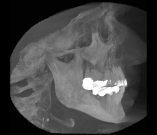
Figure 2. Maximum intensity projection (MIP) using CCD/II detector.
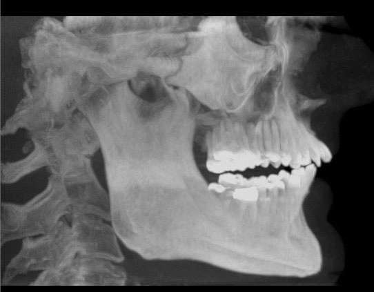
Figure 3. Maximum intensity projection (MIP) using flat panel detector.
During the reconstruction phase, the set of several hundreds of basis images will be sent to dedicated software that will then create a 3D volume reconstruction of the data volume (Figure 4) and multiplanar (MPR) reformatted images in axial, coronal, and sagittal orientation (Figure 5). The coronal images look at the patient from behind in a series of images starting at the back of the head and moving towards the face (anteroposterior view). The sagittal plane will allow evaluation of the patient’s structures from side-to-side in a series of images starting at one ear and moving to the other. The axial plane evaluates the patient from below in a series of images starting at the chin and moving to the top of the head (axial view).2
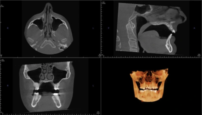
Figure 4. Multiplanar (MPR) reformatted images in axial, coronal, and sagittal orientation with 3D image.
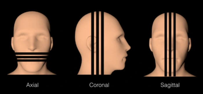
Figure 5. Reformatting in axial, coronal, and sagittal orientation
These secondary images are derived from the primary or basis images and are those that the dentist may feel most comfortable using because of the similarity to other imaging in dentistry: panoramic reconstruction, lateral cephalometric, and posteroanterior (PA) cephalometric. Perhaps the most useful secondary image in pathology and in implant planning is the cross-sectional image because it is a perpendicular view of the arch, allowing the clinician to evaluate the thickness of the alveolar crest.12 The panoramic reformatted image is often utilized among clinicians; however, attention must be made to choose a width where anatomical structures, pathoses or other structures will be shown in the image (Figure 6). The principle is similar to a panoramic projection image formation; the clinician creates a focal trough or image layer that will represent the anatomic structures shown. If the image layer selected is not of sufficient width, anatomical structures outside the selected width will not be visualized.
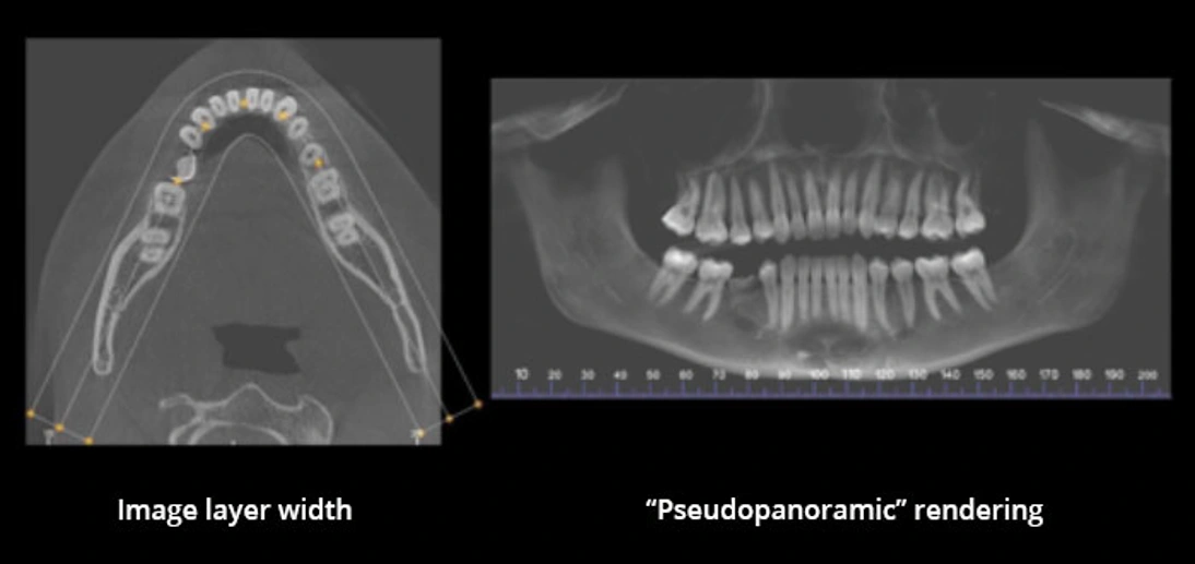
Figure 6. Axial image and pseudopanoramic rendering.